
Obstacle Avoiding Robo Kit - ElectroGlobal
The Obstacle Avoiding Robo Kit is like a friendly, DIY robot project. It uses a special sensor to see things in front of it, a moving part to look around, and controls to drive its wheels. It's smart because it can make decisions to keep itself from bumping into stuff and move around safely all by itself.
What's great is that building this robot is easy. You get a clear guide that shows you how to put all the pieces together, like a puzzle. We even give you a map of how to connect things, which is like following a recipe for making cookies. And guess what? We also share a secret code that you can put into the robot's brain (a tiny computer called Arduino). It's like teaching the robot some simple dance moves. After that, it's ready to do its thing!
In short, this robot is a fun and simple way to learn about robotics. It uses special parts to see and move, and you can build it with clear instructions. Plus, we give you the code to make it work. It's like having your own little robot friend that's good at avoiding obstacles.
Required Components:
-
- One Arduino UNO
-
- One HC-SR04 Ultrasonic Sensor
-
- One SG90 Micro Servo Motor
- .One L298N Motor Driver
-
- Four Single Shaft DC Motors
-
- One 12V Li-ion 1200mah Rechargeable Battery Pack
-
- 10 Male to Female Jumper wires
-
- 10 Male to Male Jumper wires
-
- 10 Female to Female Jumper wires
-
- Four wheels
-
- One Transparent Robot Smart Car Chassis
-
- One Mounting Bracket for Ultrasonic Sensor Module - HC-SR04
- One DC Female Connector Jack (With Wires) for Battery Packs
Components and Their Functions:
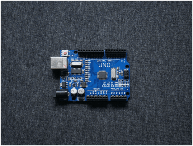
Arduino UNO
Function: The Arduino Uno is a microcontroller board that serves as the brain of your project. It's responsible for controlling all other components based on the code you program it with.
Specifications:
-
- Microcontroller: The Arduino Uno is based on the ATmega328P microcontroller from Atmel (now a part of Microchip Technology). It operates at a clock speed of 16 MHz.
- Digital I/O Pins: It has a total of 14 digital input/output pins. These pins can be used for both digital input and output operations.
- Analog Input Pins: The board has 6 analog input pins marked A0 through A5, which can be used for reading analog voltages.
- PWM (Pulse Width Modulation) Pins: There are 6 PWM output pins, which can be used for tasks such as controlling the brightness of LEDs or the speed of motors.
- Operating Voltage: The Arduino Uno can be powered either via a USB connection (5V) or an external power supply (7-12V). It has a built-in voltage regulator that regulates the voltage to 5V for the microcontroller.
- Flash Memory: It comes with 32KB of flash memory for storing your program.
- SRAM: The Uno has 2 KB of SRAM for storing variables and runtime data.
- EEPROM: It has 1KB of EEPROM, which can be used for storing non-volatile data.
- Clock Speed: The Arduino Uno operates at 16 MHz, which determines the execution speed of your program.
- USB Interface: It features a USB Type-B connector for connecting to a computer for programming and serial communication.
- Reset Button: The board includes a reset button for restarting your program.
- LEDs: There are built-in LEDs on the board, including a power LED and a built-in LED on pin 13, which is often used for testing and debugging.
- Size: The Arduino Uno board has dimensions of approximately 2.7 x 2.1 inches (68.6 x53.3 mm).
- Operating Voltage Range: The recommended operating voltage range for the Arduino Uno is 7-12V, although it can tolerate a wider range.
- Communication: The Arduino Uno can communicate with other devices via UART, SPI, and I2C protocols.
- Software: Arduino Uno is programmed using the Arduino IDE (Integrated Development Environment), which is based on the C++ programming language. It has a vast library of pre-built functions and examples for various sensors and modules.
Open Source: The Arduino platform is open-source, which means that the hardware and software designs are available for anyone to use and modify.
The Arduino Uno is a versatile and beginner-friendly board that is widely used for prototyping and learning electronics and programming. Its simplicity and strong community support make it a popular choice for makers and hobbyists.
Pin Out :
Digital Pins (D0-D13):
- D0 to D13 are digital input/output pins. These pins can be used for both digital input (reading digital signals like a button press) and digital output (controlling LEDs, relays, etc.). Pin D13 also has an onboard LED that can be used for testing and debugging.
Analog Pins (A0-A5):
- A0 to A5 are analog input pins. These pins can be used to read analog voltage levels (0-5V). They are often used to interface with sensors or read analog data.
Power Pins:
- 5V: This pin provides a regulated 5V output, which can be used to power external components.
- 3.3V: This pin provides a 3.3V regulated output.
- GND (Ground): There are several GND pins on the board, which are the ground reference for your circuits.
Other Pins:
-
- Vin: This pin allows you to provide an external voltage supply to power the Arduino Uno. It should be in the range of 7-12V.
-
- ARef: This pin can be used as a reference voltage for analog inputs.
-
- RESET: The RESET pin is used to reset the microcontroller. Communication Pins:
-
- TX (Transmit): Used for serial communication (transmit data).
-
- RX (Receive): Used for serial communication (receive data).
-
- SCL (I2C Clock): Used for I2C communication.
-
- SDA (I2C Data): Used for I2C communication.
-
- SCK (SPI Clock): Used for SPI communication.
-
- MISO (SPI Data In): Used for SPI communication.
-
- MOSI (SPI Data Out): Used for SPI communication.
-
- SS (SPI Slave Select): Used for SPI communication.
These pins are essential for connecting sensors, actuators, and other components to your Arduino Uno and for communication with other devices. Remember to consult the Arduino documentation and your specific project requirements to determine how to use these pins effectively.
Ultrasonic Sensor
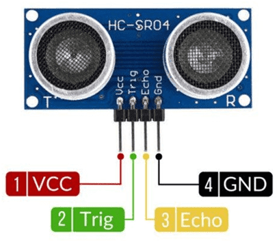
Function: The Ultrasonic Sensor (commonly an HC-SR04) is used for distance measurement. It emits ultrasonic sound waves and calculates the time it takes for the waves to bounce back, allowing you to measure distances accurately.
Specifications
-
- Operating Voltage: The HC-SR04 operates on a DC voltage ranging from 5V to 5.5V. This voltage is typically supplied by the host microcontroller or power source.
- Operating Current: It consumes around 15mA of current during operation, making it relatively power-efficient.
- Operating Frequency: The sensor emits and receives ultrasonic sound waves at a frequency of approximately 40 kHz.
- Measuring Range: The HC-SR04 has a specified measuring range of 2cm (0.79 inches) to 400cm (157.48 inches) or 4 meters. However, its accuracy and reliability decrease at longer distances, and it's most accurate within the first 2 meters.
- Resolution: The sensor provides a high-resolution measurement, typically with an accuracy of around 3mm or 0.1 inches.
- Trigger Pulse: To initiate a distance measurement, the sensor requires a 10μs (microsecond) high-level pulse on its "Trigger" pin.
- Echo Pulse: After sending an ultrasonic pulse, the sensor waits for the echo signal to return. The duration of the echo pulse is directly proportional to the distance to the object being measured.
- Minimum Object Size: The sensor can detect objects as small as the sound wave can reflect off them. However, it may have difficulty detecting very small or thin objects.
- Operating Temperature: The recommended operating temperature range for the HC-SR04 is -20°C to +70°C, or approximately -4°F to +158°F.
- Ultrasonic Transducer: The sensor consists of an ultrasonic transmitter (transducer) and a receiver. It sends out a burst of ultrasonic waves and listens for the echo to calculate the distance.
- Output: The HC-SR04 provides a digital output on its "Echo" pin, which goes high when it receives an echo. The duration of the high signal is proportional to the distance.
- Dimensions: The sensor module is small and compact, typically measuring about 45mm x 20mm x 15mm (L x W x H).
- Operating Mode: The sensor operates in a non-contact mode, making it suitable for applications where physical contact with the target is not desirable.
- Interface: It's easy to interface the HC-SR04 with microcontrollers like Arduino, Raspberry Pi, or other platforms. It requires two digital pins (Trigger and Echo) for communication.
- Angle of Detection: The sensor typically has a detection angle of about 15 degrees, so it may not detect objects located outside of this cone.
The HC-SR04 Ultrasonic Sensor is widely used for distance measurement and obstacle detection in various applications, including robotics, automation, and IoT projects. Its low cost, simplicity, and relatively long-range capability make it a popular choice for many makers and hobbyists.
Pin Out:
-
- VCC (or +5V): This is the power supply pin. Connect it to the 5V output of your microcontroller or power source.
-
- Trig (or Trigger): This is the trigger input pin. To start a distance measurement, you need to send a 10μs (microsecond) high-level pulse to this pin. You can control this pin using a digital output pin from your microcontroller.
-
- Echo: This is the echo output pin. After sending the ultrasonic pulse, the sensor listens for the echo signal to return. The duration of the high-level signal on this pin is directly proportional to the time it takes for the ultrasonic waves to bounce off an object and return. You can measure this duration using a digital input pin on your microcontroller.
-
- GND (or Ground): This is the ground or common reference pin. Connect it to the ground (0V) of your microcontroller or power source to complete the circuit.
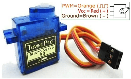
Servo Motor
Function: A servo motor is used to control the orientation of your robot's sensor or any other parts that need precise angular control. It can move within a specified range, making it suitable for tasks like steering.
Specifications
-
- Type: Servo motors are typically classified into two main types: analog and digital (also known as digital servos).
- Operating Voltage: Servo motors operate within a specified voltage range, typically between 4.8V and 7.4V for standard models. High-voltage servos can operate at voltages up to 8.4V or more.
- Torque Rating: The torque rating of a servo motor indicates the amount of rotational force it can exert. It is typically specified in ounce-inches (oz-in) or kilogram-centimeters (kg-cm). Higher torque ratings indicate greater strength.
- Speed: The speed of a servo motor is specified in terms of how quickly it can rotate the output shaft. It is typically measured in seconds per 60 degrees of rotation or in degrees per second.
- Operating Angle: Servo motors are designed to rotate within a specific angle range, often 90 to 180 degrees. Some models offer continuous rotation for applications that require it.
- Control Interface: Servo motors are controlled using pulse-width modulation (PWM) signals. The most common PWM signal has a period of 20ms, with the pulse width varying between 1ms (minimum position) and 2ms (maximum position) for a standard 180-degree servo.
- Feedback System: Servo motors incorporate a feedback system, such as a potentiometer or an encoder, to provide position feedback to the controller. This feedback allows the controller to adjust the motor's position accurately.
- Operating Temperature: Servo motors are designed to operate within a specified temperature range, which can vary depending on the model. Typical ranges might be from -10°C to +60°C.
- Weight: The weight of a servo motor is an important consideration, especially in applications where weight is a critical factor, such as drones or robotics.
- Dimensions: Servo motors come in various sizes, and their physical dimensions, including the length, width, and height, can vary significantly.
- Operating Noise: Servo motors can produce mechanical noise during operation, which may be a consideration in noise-sensitive applications.
- Duty Cycle: The duty cycle of a servo motor indicates the percentage of time it can operate continuously without overheating. It's essential to stay within the specified duty cycle to avoid damage to the motor.
- Voltage Compatibility: Some servo motors are designed to operate at different voltage levels, and they may have a voltage compatibility range specified in their datasheets.
- Gear Type: Servo motors often incorporate gear systems to increase torque and reduce the speed of the motor's output shaft. The type and quality of gears can vary between models.
- Construction: Servo motors can have various construction types, such as coreless, brushed, or brushless, which can impact their performance and durability.
Pin Out :
-
- Signal (or Control) Wire (usually yellow or white): This wire is responsible for carrying the control signal from your microcontroller or servo controller to the servo motor. It typically connects to a PWM (Pulse Width Modulation) output pin on your controller. The width of the PWM signal pulse determines the position of the servo's shaft.
-
- the positive voltage supply, typically within the range of 4.8V to 7.4V, depending on the servo's specifications. It provides the electrical power necessary to operate the motor.
-
- Ground Wire (usually brown or black): The ground wire is connected to the ground (0V) of your power supply and microcontroller. It serves as the reference voltage for the servo's operation.
Single Shaft DC Motors
Function: These motors are used for driving the wheels of your robot. You mentioned four of them, likely for controlling the movement of the robot in different directions.
Specifications:
-
- Operating Voltage: Single shaft DC motors typically operate within a specific voltage range, which can vary depending on the model. Common voltage ranges might include 3V, 6V, 12V, or other values.
- No-Load Speed: This is the speed at which the motor shaft rotates when no load or external resistance is applied to it. It is usually measured in revolutions per minute (RPM) or rotations per minute.
- Stall Current: The stall current is the maximum current the motor draws when the shaft is prevented from rotating (i.e., it's "stalled"). This specification is essential for sizing the motor driver or power supply.
- Stall Torque: Stall torque is the maximum torque the motor can generate when it's prevented from rotating. It's typically measured in ounce-inches (oz-in) orNewton-meters (N•m).
- Rated Voltage: Some motors have a rated voltage, which is the voltage at which their performance specifications (such as speed and torque) are defined. It's often the voltage at which the motor operates most efficiently.
- Motor Type: Motors can be brushed or brushless. Brushed motors have brushes and a commutator, while brushless motors do not. Brushless motors tend to be more efficient and have a longer lifespan but are often more expensive.
- Shaft Diameter: The diameter of the motor shaft can vary, and it's important to know this dimension if you plan to attach accessories or wheels to the motor.
- Dimensions: The physical size of the motor, including its length and diameter, can vary. These dimensions are crucial if you have specific space constraints in your project.
- Operating Temperature Range: Some motors have specified operating temperature ranges. It's important to stay within this range to ensure the motor's proper function.
- Weight: The weight of the motor can be a factor in applications where weight is a critical consideration, such as robotics or drones.
- Efficiency: Some motors provide information about their efficiency, which indicates how effectively they convert electrical power into mechanical power. Higher efficiency is generally desirable.
- Construction Material: The materials used in the motor's construction, such as the casing and the type of magnets used, can affect its durability and performance.
- Encoder Compatibility: In some cases, motors are designed to work with encoders for precise position or speed control.
- Gearbox Compatibility: Motors are often used with gearboxes to achieve the desired speed or torque. Compatibility with specific gearbox models may be a consideration.
Pin Out :
-
- Positive Terminal (usually red or marked with "+"): This wire is connected to the positive voltage supply, typically within the specified voltage range for the motor (e.g., 3V, 6V, 12V, etc.).
-
- Negative Terminal (usually black or marked with "-"): This wire is connected to the ground (0V) of your power supply.

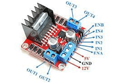
L298N Motor Driver
Function: The L298N is a motor driver module that allows you to control the direction and speed of DC motors. It's crucial for controlling your robot's movement.
Specifications:
-
- Motor Compatibility: The L298N motor driver is designed to control two DC motors or one bipolar stepper motor.
- Operating Voltage: It can operate with a wide range of supply voltages, typically from 4.5V to 46V. The recommended operating voltage is often around 7V to 35V.
- Maximum Current Handling: The L298N can handle a maximum current of around 2A per channel (for each motor output), making it suitable for a wide range of motors.
- Motor Output Channels: The L298N has two output channels (dual H-bridge configuration), allowing you to control two motors independently.
- Built-in Protection: It includes built-in protection features such as thermal shutdown and overcurrent protection to prevent damage to the IC and motors.
- Logic Compatibility: The L298N can be controlled using logic-level inputs. It accepts both TTL and CMOS logic levels, making it compatible with various microcontrollers and control systems.
- Control Modes: It can operate in various control modes, including forward, reverse, brake, and freewheeling, allowing you to control motor direction and speed.
- Operating Temperature Range: The IC can typically operate within a temperature range of -25°C to +130°C, although specific limits may vary depending on the manufacturer.
- Heat Sink: Many L298N modules come with a built-in heat sink or a provision to attach an external heat sink, which can be essential for dissipating heat generated during motor operation.
- Voltage Regulator: Some L298N modules include a 5V voltage regulator to provide a regulated 5V output, which can be used to power external control circuitry.
- Control Interface: The L298N typically requires four digital input pins for controlling two motors, with additional pins for enabling and disabling each motor output.
- Dimensions: The L298N is available in various package types, but it is commonly found in a multi-pin DIP (Dual Inline Package) or on pre-made motor driver modules with convenient screw terminals.
- Efficiency: The efficiency of the L298N motor driver can vary based on the operating conditions and voltage levels. It may generate some heat during operation, especially when driving high-current loads, so heat management is important.
- Applications: The L298N motor driver is widely used in robotics, automation, and DIY projects to control motors for tasks such as movement, conveyor belt control, and more.
Pin Out:
Motor A Connections:
-
- Input 1A (INA): Control input for Motor A, used for forward motion control.
-
- Input 1B (INB): Control input for Motor A, used for reverse motion control.
-
- Enable 1A (ENA): Enable input for Motor A, activating this pin allows control of Motor A.
-
- GND (Ground): Connect to the common ground of your power supply and microcontroller.
-
- VCC (Motor Supply Voltage): Connect to the supply voltage for Motor A.
-
- GND (Ground): Common ground for both motors and the internal circuitry.
-
- Output 1A (OUTA): Motor A output terminal (connects to one terminal of the motor).
-
- Output 1B (OUTB): Motor A output terminal (connects to the other terminal of the motor).
-
- Enable 1B (ENB): Enable input for Motor A, activating this pin allows control of Motor A.
Motor B Connections:
-
- Input 2A (INB): Control input for Motor B, used for forward motion control.
-
- Input 2B (INC): Control input for Motor B, used for reverse motion control.
-
- Enable 2A (ENB): Enable input for Motor B, activating this pin allows control of Motor B.
-
- GND (Ground): Connect to the common ground of your power supply and microcontroller.
-
- VCC (Motor Supply Voltage): Connect to the supply voltage for Motor B.
-
- GND (Ground): Common ground for both motors and the internal circuitry.
-
- Output 2A (OUTC): Motor B output terminal (connects to one terminal of the motor).
-
- Output 2B (OUTD): Motor B output terminal (connects to the other terminal of the motor).
-
- Enable 2B (ENC): Enable input for Motor B, activating this pin allows control of Motor B.
12V Li-ion Battery
Function: This battery provides power to the motors and other components, ensuring they have the necessary energy to operate.
Specifications:
-
- Voltage: A 12V Li-ion battery typically has a nominal voltage of 12 volts. The voltage can vary slightly depending on the state of charge, with a fully charged battery having a voltage slightly higher than 12V.
- Capacity (mAh or Ah): Capacity is a measure of the amount of energy a battery can store. It is usually specified in milliampere-hours (mAh) or ampere-hours (Ah). Common capacities for 12V Li-ion batteries range from a few hundred milliampere-hours (mAh) to several ampere-hours (Ah).
- Chemistry: Li-ion batteries use lithium-ion chemistry, which provides a good balance between energy density and weight.
- Cycle Life: Cycle life indicates how many charge and discharge cycles a battery can undergo before its capacity significantly degrades. High-quality Li-ion batteries can have several hundred to over a thousand charge cycles.
- Operating Temperature Range: Li-ion batteries typically operate within a specified temperature range. The range can vary, but it is often around -20°C to +60°C (-4°F to+140°F).
- Self-Discharge Rate: Li-ion batteries have a relatively low self-discharge rate, meaning they can hold their charge for extended periods when not in use. The self-discharge rate is typically less than 1% per month.
- Size and Form Factor: The physical size and form factor of a 12V Li-ion battery can vary widely. Common form factors include cylindrical cells, prismatic cells, and pouch cells.
- Weight: The weight of a 12V Li-ion battery depends on its capacity and form factor. Smaller batteries can weigh just a few ounces, while larger ones can weigh several pounds or more.
- Protection Circuit: Some 12V Li-ion batteries come with a built-in protection circuit that safeguards against overcharging, over-discharging, and short-circuiting.
- Charging Method: Li-ion batteries typically require a specific charging method to ensure safety and longevity. This may involve using a dedicated Li-ion battery charger with the appropriate voltage and current settings.
- Applications: 12V Li-ion batteries are commonly used in various applications, including portable electronics, power banks, electric vehicles, solar energy storage systems, and more.
- Certifications: High-quality Li-ion batteries may have safety certifications, such as UL (Underwriters Laboratories) or CE (Conformité Européenne), to ensure compliance with safety standards.
Pin Out:
-
- Positive Terminal (+): This terminal is the positive (anode) side of the battery, and it provides the higher voltage potential. You connect your load or device's positive input to this terminal.
-
- Negative Terminal (-): This terminal is the negative (cathode) side of the battery, and it serves as the ground or common reference. You connect your load or device's negative input to this terminal.
- Negative Terminal (-): This terminal is the negative (cathode) side of the battery, and it serves as the ground or common reference. You connect your load or device's negative input to this terminal.
/*! elementor - v3.16.0 - 09-10-2023 */
.elementor-widget-image{text-align:center}.elementor-widget-image a{display:inline-block}.elementor-widget-image a img[src$=".svg"]{width:48px}.elementor-widget-image img{vertical-align:middle;display:inline-block} 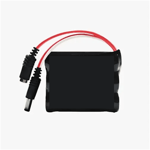
Connections:
Motor Driver Connections with Arduino:
in1: Connect to Arduino pin D7. This controls the direction of one of your motors.
in2: Connect to Arduino pin D6. This controls the direction of the same motor as in1.
in3: Connect to Arduino pin D5. This controls the direction of another motor.
in4: Connect to Arduino pin D4. This controls the direction of the same motor as in3.
Ultrasonic Sensor Connections with Arduino:
VCC: Connect to 5V on the Arduino to power the sensor.
Trig: Connect to Arduino pin A1. This is the trigger pin for sending the ultrasonic signal.
Echo: Connect to Arduino pin A2. This is the echo pin for receiving the reflected signal.
GND: Connect to the ground (GND) on the Arduino.
Servo Motor Connection with Arduino:
GND: Connect to the ground (GND) on the Arduino.
VCC: Connect to 5V on the Arduino to power the servo.
SIG: Connect to Arduino pin D10. This is the signal pin for controlling the servo's position.
Additional Considerations:
Make sure to connect the grounds of all components together to create a common ground reference.
You'll need to write Arduino code to control these components effectively. The code will involve reading data from the ultrasonic sensor to detect obstacles and controlling the motors via the motor driver to navigate around obstacles.
With these connections and some well-written Arduino code, your obstacle-avoiding robot should be able to sense obstacles using the ultrasonic sensor and maneuver around them using the servo and motors.
/*! elementor - v3.16.0 - 09-10-2023 */
.elementor-heading-title{padding:0;margin:0;line-height:1}.elementor-widget-heading .elementor-heading-title[class*=elementor-size-]>a{color:inherit;font-size:inherit;line-height:inherit}.elementor-widget-heading .elementor-heading-title.elementor-size-small{font-size:15px}.elementor-widget-heading .elementor-heading-title.elementor-size-medium{font-size:19px}.elementor-widget-heading .elementor-heading-title.elementor-size-large{font-size:29px}.elementor-widget-heading .elementor-heading-title.elementor-size-xl{font-size:39px}.elementor-widget-heading .elementor-heading-title.elementor-size-xxl{font-size:59px}
Code :
					#include           // Include the Servo motor library.
#include         // Include the Ultrasonic sensor function library. You must install this library.
// Define our L298N control pins
const int LeftMotorForward = 7;
const int LeftMotorBackward = 6;
const int RightMotorForward = 5;
const int RightMotorBackward = 4;
// Define sensor pins
#define trig_pin A1         // Define the trigger pin for the ultrasonic sensor (analog input 1)
#define echo_pin A2         // Define the echo pin for the ultrasonic sensor (analog input 2)
#define maximum_distance 200 // Define the maximum allowable distance for the ultrasonic sensor
boolean goesForward = false; // A boolean flag to track if the robot is moving forward
int distance = 150;          // Initialize a variable to store distance
NewPing sonar(trig_pin, echo_pin, maximum_distance); // Create an instance of the NewPing library for the ultrasonic sensor
Servo servo_motor;            // Create a Servo object named servo_motor
void setup() {
  pinMode(RightMotorForward, OUTPUT);  // Set the right motor forward pin as an output
  pinMode(LeftMotorForward, OUTPUT);   // Set the left motor forward pin as an output
  pinMode(LeftMotorBackward, OUTPUT);  // Set the left motor backward pin as an output
  pinMode(RightMotorBackward, OUTPUT); // Set the right motor backward pin as an output
  servo_motor.attach(10);   // Attach the servo to pin 10
  servo_motor.write(82);    // Set the initial servo position to 82 degrees
  delay(2000);              // Delay for 2 seconds
  // Read the initial distance from the ultrasonic sensor
  distance = readPing();
  delay(100);
  distance = readPing();
  delay(100);
  distance = readPing();
  delay(100);
  distance = readPing();
  delay(100);
}
void loop() {
  int distanceRight = 0;  // Initialize a variable to store the distance to the right
  int distanceLeft = 0;   // Initialize a variable to store the distance to the left
  delay(50);
  if (distance = distanceLeft) { // Check if the distance to the left is greater than or equal to the current distance
      turnRight();                 // Call the turnRight function to turn the robot right
      moveStop();                  // Call the moveStop function to stop the robot
    } else {
      turnLeft();                  // Call the turnLeft function to turn the robot left
      moveStop();                  // Call the moveStop function to stop the robot
    }
  } else {
    moveForward();               // Call the moveForward function to move the robot forward
  }
  // Read the distance from the ultrasonic sensor
  distance = readPing();
}
// Function to move the servo to the right and measure distance
int lookRight() {
  servo_motor.write(20);   // Set the servo angle to 20 degrees (move right)
  delay(500);
  int distance = readPing(); // Call the readPing function to measure the distance
  delay(100);
  servo_motor.write(82);     // Reset the servo to the center position (82 degrees)
  return distance;           // Return the measured distance
}
// Function to move the servo to the left and measure distance
int lookLeft() {
  servo_motor.write(170);  // Set the servo angle to 170 degrees (move left)
  delay(500);
  int distance = readPing(); // Call the readPing function to measure the distance
  delay(100);
  servo_motor.write(82);     // Reset the servo to the center position (82 degrees)
  return distance;           // Return the measured distance
}
// Function to read the distance from the ultrasonic sensor
int readPing() {
  delay(70);                 // Delay for a short time
  int cm = sonar.ping_cm();  // Call the ping_cm function to read the distance in centimeters from the ultrasonic sensor
  if (cm == 0) {
    cm = 250;                // If the distance is zero, set it to a default value of 250 (max_distance)
  }
  return cm;                 // Return the measured distance in centimeters
}
// Function to stop the movement of both motors
void moveStop() {
  digitalWrite(RightMotorForward, 0);
  digitalWrite(LeftMotorForward, 0);
  digitalWrite(RightMotorBackward, 0);
  digitalWrite(LeftMotorBackward, 0);
}
// Function to move forward
void moveForward() {
  if (!goesForward) {
    goesForward = true;
    digitalWrite(LeftMotorForward, 105);
    digitalWrite(RightMotorForward, 105);
    digitalWrite(LeftMotorBackward, 0);
    digitalWrite(RightMotorBackward, 0);
  }
}
// Function to move backward
void moveBackward() {
  goesForward = false;
  digitalWrite(LeftMotorBackward, 105);
  digitalWrite(RightMotorBackward, 105);
  digitalWrite(LeftMotorForward, 0);
  digitalWrite(RightMotorForward, 0);
}
// Function to turn the robot to the right
void turnRight() {
  digitalWrite(LeftMotorForward, 105);
  digitalWrite(RightMotorBackward, 105);
  digitalWrite(LeftMotorBackward, 0);
  digitalWrite(RightMotorForward, 0);
  delay(250);
  digitalWrite(LeftMotorForward, 105);
  digitalWrite(RightMotorForward, 105);
  digitalWrite(LeftMotorBackward, 0);
  digitalWrite(RightMotorBackward, 0);
}
// Function to turn the robot to the left
void turnLeft() {
  digitalWrite(LeftMotorBackward, 105);
  digitalWrite(RightMotorForward, 105);
  digitalWrite(LeftMotorForward, 0);
  digitalWrite(RightMotorBackward, 0);
  delay(250);
  digitalWrite(LeftMotorForward, 105);
  digitalWrite(RightMotorForward, 105);
  digitalWrite(LeftMotorBackward, 0);
  digitalWrite(RightMotorBackward, 0);
}
Explanation of code:
Here's an explanation of how this code works:
1.Library Inclusions
The code begins by including two essential libraries: Servo.h and NewPing.h. These libraries facilitate servo motor control and ultrasonic distance sensor interfacing, respectively. The inclusion of NewPing.h is particularly significant as it enables the Arduino to interact with the ultrasonic sensor.
- Pin Configuration
The next section of the code defines the various pin configurations. These pin definitions serve to establish the connections between the Arduino and the physical components of the robot:
Motor Control Pins:
LeftMotorForward, LeftMotorBackward, RightMotorForward, and RightMotorBackward represent pins used to control the robot's two DC motors, presumably connected to an L298N motor driver.
Sensor Pins:
trig_pin and echo_pin denote the trigger and echo pins of the ultrasonic sensor, respectively. These pins are analog inputs used for measuring distances.
Distance Limit:
maximum_distance is a constant representing the maximum distance (in centimeters) that the ultrasonic sensor can measure. This limit is set to 200 cm.
- Variable Declarations
The code declares several variables to manage the robot's behavior and sensor readings:
goesForward: A boolean variable that tracks whether the robot is currently moving forward.
distance: An integer variable used to store the distance measured by the ultrasonic sensor.
sonar: An instance of the NewPing library that interfaces with the ultrasonic sensor.
servo_motor: An instance of the Servo library used to control a servo motor for scanning.
- Setup Function
In the setup() function, the code initializes the robot's components and prepares them for operation:
Motor control pins are configured as outputs.
The servo motor is attached to pin 10 and positioned at 82 degrees.
The code delays for 2 seconds to allow the servo motor to settle.
Initial distance readings are taken from the ultrasonic sensor for calibration purposes.
- Main Loop Function
The loop() function is the main execution loop of the program, where the robot's behavior is defined. It continuously monitors the environment for obstacles and reacts accordingly:
The distance to the nearest obstacle is measured.
If the measured distance is less than or equal to 100 cm, the robot initiates obstacle avoidance maneuvers:
It stops moving (moveStop()).
Reverses for 400 ms (moveBackward()).
Stop again.
Scans to the right and left to determine the distances (lookRight() and lookLeft()).
Based on the measured distances, it decides to turn right or left and takes the appropriate action.
If the measured distance is greater than 100 cm, the robot continues moving forward.
- Helper Functions
The code contains several helper functions to streamline operations:
lookRight() and lookLeft(): These functions control the servo motor's position to scan the environment on the right and left sides, respectively, to measure distances.
readPing(): This function reads the distance from the ultrasonic sensor and returns the result in centimeters.
moveStop(), moveForward(), moveBackward(), turnRight(), and turnLeft(): These functions manage the robot's movements, including stopping, moving forward/backward, and making right or left turns.
Image Gallery
Quote of the Day
Style is more than what we wear or how we decorate our spaces — it’s the freedom to choose what reflects who we are. Every design, every detail, is crafted with intention: to inspire joy, to add meaning, and to transform the everyday into something extraordinary. Because when comfort meets elegance, life itself feels more beautiful.
Brand Description
At our core, we believe that style should feel effortless yet meaningful. Each collection is carefully designed with attention to detail, blending modern aesthetics with everyday comfort. From timeless silhouettes to refined textures, our pieces are crafted to inspire confidence and elevate the way you live and dress. More than fashion, it’s a lifestyle made for you.
Current Top Sellers